1. Introduction: The Critical Role of Laser Drilling in TGV Fabrication
2.4. Step 4: Glass Via Formation – Achieving Quality Sidewalls
2.6. Step 6: Metallisation – From Glass Via to Conductive TGV
4. Advanced Considerations – High Aspect Ratio and Thin Glass
7. Conclusion: Laser Drilling – The Enabler of Glass Interposer Technology
1. Introduction: The Critical Role of Laser Drilling in TGV Fabrication
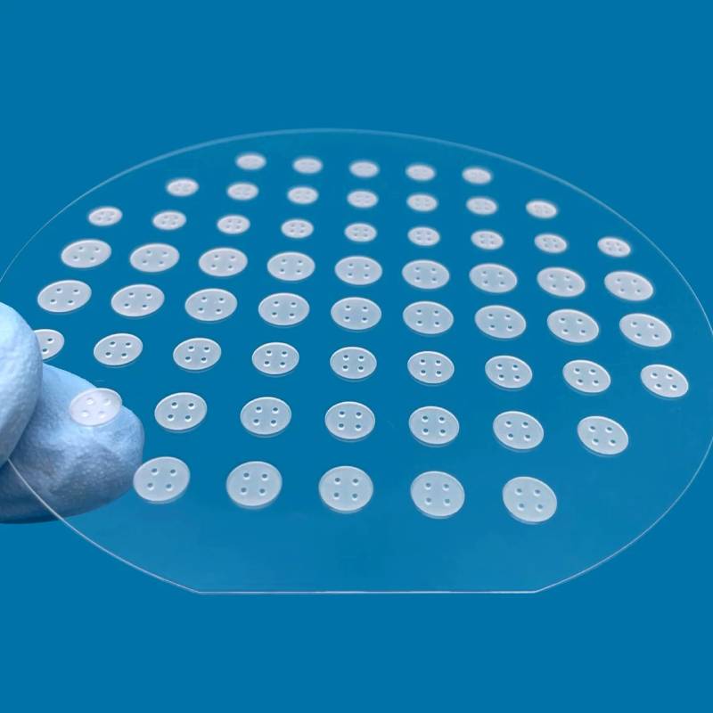
Through‑Glass Vias (TGVs) are the vertical lifelines of glass interposer technology. They are the tiny, metallised holes that pierce through a glass substrate, enabling electrical signals and power to travel from one side of the interposer to the other. Without TGVs, the advantages of glass – low dielectric loss, CTE tuneability, and large‑area panel processing – would remain unusable for advanced packaging.
However, creating a TGV is fundamentally different from creating a via in silicon. Glass is amorphous, brittle, and chemically inert to standard anisotropic etchants. Laser drilling is the mainstream industrially viable method for producing high‑quality, high‑aspect‑ratio vias in glass.
This article explains exactly how laser drilling creates Through‑Glass Vias – from the physics of the laser pulse interacting with the glass, to material removal, via formation, and the critical steps leading to metallisation.
2. The TGV Laser Process – Step‑by‑Step Overview
The complete TGV laser drilling process can be broken down into six distinct phases, each of which must be carefully controlled to achieve a reliable via suitable for metallisation.
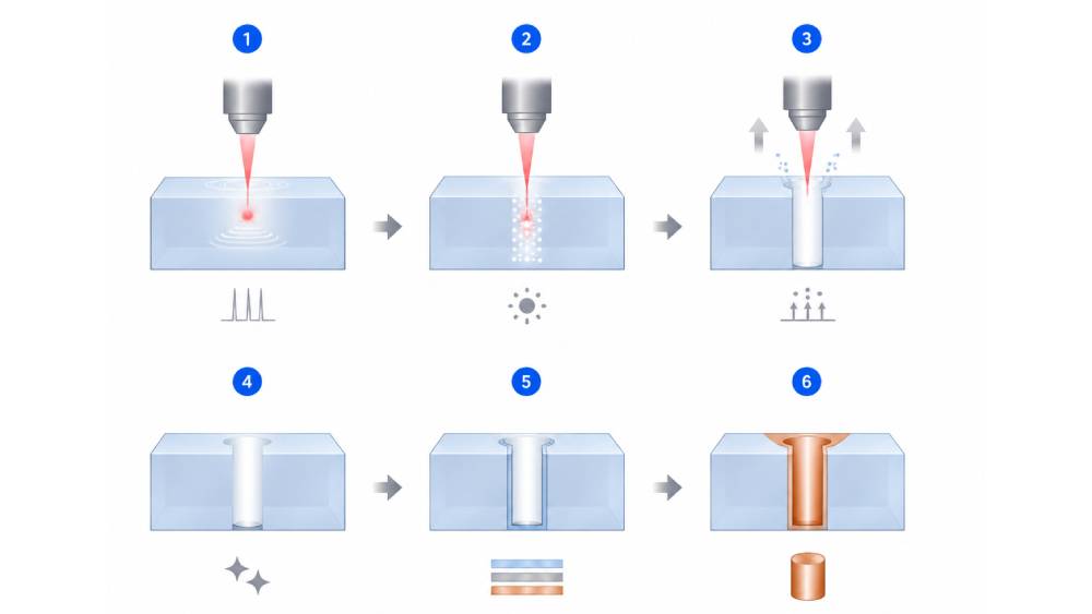
2.1. Step 1: Laser Pulse Generation and Delivery
The process begins with the laser source. Industrial TGV drilling is predominantly performed using UV picosecond lasers (355 nm) – the optimal balance of cold ablation quality, sidewall smoothness, and throughput within the ultrafast laser category.
Ultra‑short pulse width (<10 ps) ensures that energy is deposited before heat can diffuse into the surrounding glass, enabling "cold ablation."
UV wavelength (355 nm) provides high photon energy, which couples efficiently with the glass via nonlinear absorption mechanisms (multi‑photon ionisation).
High repetition rate (200–800 kHz) enables fast material removal and industrial throughput.
The laser beam is delivered through a galvanometer scanner and an F‑theta lens, which focuses the beam to a small spot (typically 10–30 µm in diameter) and steers it across the glass surface at high speed.
For thick glass (>300 µm) or high aspect ratios, ensure your laser system has dynamic Z‑axis focus tracking – the focal plane must move downward as the via deepens to maintain constant fluence at the bottom of the hole.
2.2. Step 2: Nonlinear Absorption and Internal Modification
When the focused picosecond laser pulse strikes the glass surface, the energy density at the focal point is extremely high (GW/cm² to TW/cm²). At these intensities, the glass does not simply absorb the light linearly; instead, nonlinear absorption occurs:
Multi‑photon ionisation – multiple photons are absorbed simultaneously to excite electrons across the bandgap.
Avalanche ionisation – free electrons are accelerated by the electric field, colliding with lattice atoms and creating a cascade of ionisation.
This process creates a micro‑plasma within the glass at the focal point. Depending on the laser parameters and focus position, two distinct regimes are possible:
| Regime | Description | Typical Application |
|---|---|---|
| Surface ablation | Focus is on the glass surface; material is vaporised from the top down. | Thin glass (<100 µm), large‑diameter vias. |
| Internal modification | Focus is slightly below the surface; the laser modifies a buried layer, which is later removed by chemical etching or subsequent passes. | High‑aspect‑ratio vias, crack‑free drilling. |
For most industrial TGV drilling, surface ablation with multi‑pass trepanning is preferred because it directly removes material and provides real‑time process control.
2.3. Step 3: Material Removal – Trepanning and Ablation
Once the laser energy is absorbed, the glass at the focal point undergoes rapid heating, melting, and vaporisation. The rapid expansion creates a high‑pressure plume that ejects molten and solid particles from the hole. This is material removal by ablation.
To create a cylindrical via with vertical sidewalls, a trepanning (spiral) drilling strategy is employed:
The laser beam traces a series of concentric circles or a continuous spiral from the centre outward.
Each pass removes a thin layer of glass (2–5 µm).
The beam gradually increases in radius, enlarging the hole to the final target diameter.
This approach produces a nearly cylindrical via with minimal taper.
Critical parameters for material removal efficiency:
| Parameter | Typical Range / Setting | Impact |
|---|---|---|
| Pulse energy | 10–50 µJ | Higher energy removes more material per pulse but risks micro‑cracks. |
| Spot size | 10–30 µm | Smaller spots give finer control; larger spots increase removal rate. |
| Trepanning radius increment | 1–3 µm per revolution | Smaller increments yield smoother sidewalls. |
| Number of passes | 10–50 (depending on glass thickness) | Each pass deepens the hole by a few microns. |
| Scan speed | 100–500 mm/s | Slower speeds increase material removal per pass but reduce throughput. |
| Assist gas | Nitrogen or dry air at 1–3 bar | Removes debris; prevents redeposition inside the via. |
For aspect ratios >10:1 (e.g., 50 µm diameter, 500 µm depth), reduce the pulse energy and increase the number of passes to prevent glass cracking at the via bottom.
2.4. Step 4: Glass Via Formation – Achieving Quality Sidewalls
The formed via must meet strict quality criteria before it can be metallised. The key quality indicators are:
| Indicator | Acceptance Criterion | Why It Matters |
|---|---|---|
| Sidewall roughness (Ra) | ≤0.5 µm | Rough sidewalls cause poor adhesion of barrier/seed layers and create voids during copper fill. |
| Taper angle | ≤2° (near‑vertical) | Excessive taper reduces the usable cross‑section for electrical conduction. |
| Micro‑cracks | None – verified by SEM cross‑section | Cracks propagate during thermal cycling, causing via failure. |
| Debris / residue | Minimal – no large particles inside the via | Debris blocks seed layer deposition and creates plating voids. |
| Top and bottom edge quality | No chipping or spalling | Chips compromise the integrity of the redistribution layer (RDL) on both surfaces. |
How the laser achieves these:
Picosecond pulses minimise the heat‑affected zone (HAZ) – the glass adjacent to the via remains unchanged.
Proper trepanning overlap (typically 60–80% between successive spirals) ensures a smooth wall.
Dynamic Z‑tracking maintains the focus at the bottom of the via throughout the drilling process, ensuring uniform energy density from top to bottom.
2.5. Step 5: Cleaning and Preparation for Metallisation
After laser drilling, the via is not immediately ready for copper filling. The ablation process leaves:
Nanoparticles and debris adhering to the sidewalls.
A micro‑rough surface (even if Ra is <0.5 µm, there may be loose particles).
A thin re‑deposited layer of glass (recast) on the sidewalls.
Post‑drill cleaning steps:
Ultrasonic cleaning – in deionised water or a mild solvent, to dislodge loose particles.
Wet chemical etching – a brief (5–30 seconds) dip in dilute hydrofluoric acid (HF) or a buffered oxide etch. This removes the recast layer and slightly smooths the sidewalls.
Rinsing and drying – to remove any chemical residues.
2.6. Step 6: Metallisation – From Glass Via to Conductive TGV
With the via cleaned and sidewalls conditioned, the final step is metallisation, which converts the glass hole into an electrical conductor.
The standard metallisation sequence is:
| Sub‑Step | Process | Details |
|---|---|---|
| Barrier layer | Sputtering (PVD) | Deposits a thin (50–200 nm) adhesion layer – typically Ti, TiW, or Cr – on the sidewall. |
| Seed layer | Sputtering (PVD) | Deposits a copper seed layer (200–500 nm) on top of the barrier. |
| Copper fill | Electrolytic plating | Fills the via from the bottom up with solid copper, using the seed layer as the cathode. |
| Planarisation | CMP or grinding | Removes the copper overburden from the glass surfaces. |
Note: Because glass is an insulator, no dielectric liner (like the SiO₂ liner required for TSVs) is needed. This simplifies the metallisation process and reduces cost.
3. Key Process Parameters – A Practical Tuning Guide
For engineers setting up a TGV laser drilling process, the following table provides a starting point and tuning direction:
| Parameter | Starting Point | If Via Is Too Rough | If Via Has Cracks | If Throughput Is Too Low |
|---|---|---|---|---|
| Pulse energy | 20 µJ | Decrease by 10–20% | Decrease by 20–30% | Increase by 10–15% (check for cracks) |
| Repetition rate | 500 kHz | Decrease to reduce heat accumulation | Decrease | Increase (but monitor heat) |
| Scan speed | 300 mm/s | Decrease (more overlap = smoother) | Increase (less heat per spot) | Increase (up to 500–800 mm/s) |
| Assist gas pressure | 2 bar (N₂) | Increase to clear debris | Ensure gas is dry; increase flow | Optimise for debris removal |
| Number of passes | 20 (for 300 µm glass) | Increase for smoother walls | Decrease to reduce thermal stress | Decrease with higher pulse energy |
| Focus position | On surface | Slight defocus (+1 mm) for wider top | Ensure dynamic Z‑tracking is active | Use dynamic tracking to maintain focus |
4. Advanced Considerations – High Aspect Ratio and Thin Glass
4.1. High Aspect Ratio (>10:1)
Use lower pulse energy and smaller incremental depth per pass (2–3 µm per pass).
Apply a slight positive taper (top slightly wider than bottom) to reduce stress and assist copper plating.
Helium assist gas (instead of nitrogen) improves debris evacuation in deep, narrow vias.
4.2. Ultra‑Thin Glass (<100 µm)
Risk of backside chipping is high. Reduce pulse energy and increase the number of passes.
Use a support film or vacuum chuck to prevent vibration.
Drill from both sides (front and back) to meet in the middle – this halves the required depth per side and reduces taper.
5. Quality Assurance and Defect Mitigation
| Defect | Visual / Test Finding | Root Cause | Corrective Action |
|---|---|---|---|
| Sidewall roughness >1 µm | Rough, textured walls seen in SEM | Insufficient trepanning overlap; too high pulse energy | Reduce pulse energy; decrease scan speed; reduce spiral step increment. |
| Micro‑cracks at via rim | Hairline cracks radiating from top edge | Thermal shock – too high energy or too few passes | Reduce pulse energy; increase number of passes; use ps instead of ns. |
| Debris blocking the via | Particles visible inside the hole | Poor assist gas or insufficient cleaning | Increase gas pressure; add an ultrasonic cleaning step after drilling. |
| Taper angle >5° | Hole visibly conical in cross‑section | Dynamic Z‑tracking not active; focus shifted | Enable dynamic focus; verify calibration; reduce trepanning radius growth rate. |
| Incomplete drilling (not through) | Blind via instead of through‑hole | Insufficient number of passes | Increase passes; slightly increase pulse energy for final breakthrough pass. |
| Post‑metallisation void | Plated via shows empty spaces (SEM) | Sidewall debris or roughness causing poor seed layer | Improve pre‑plating cleaning; reduce sidewall roughness; verify seed layer continuity. |
6. Comparison with Other Via Drilling Methods in Glass
| Method | Suitability for TGV | Limitations |
|---|---|---|
| CO₂ laser drilling | Poor – thermal melting creates large HAZ, micro‑cracks, and rough walls. | Not used for high‑reliability TGV. |
| Femtosecond laser drilling | Excellent – ultimate quality, minimal damage. | Lower throughput, higher cost – used mainly for R&D and ultra‑critical applications. |
| Picosecond UV laser drilling | Optimal – best balance of quality, speed, and cost. | Requires careful parameter tuning – standard for industrial TGV production. |
| Wet chemical etching (HF) | Low – isotropic, dangerous, limited aspect ratio. | Not viable for high‑density arrays. |
| Mechanical drilling | Not suitable – glass is brittle; high tool wear and chipping. | Only for large, non‑critical holes. |
7. Conclusion: Laser Drilling – The Enabler of Glass Interposer Technology
The laser drilling process for TGV is a carefully orchestrated sequence of:
Ultrashort pulse generation – using picosecond UV lasers for cold ablation.
Nonlinear absorption – coupling energy into the glass without thermal damage.
Trepanning material removal – layer‑by‑layer creation of a smooth, vertical via.
Meticulous cleaning – preparing the sidewalls for metallisation.
Copper filling – transforming the glass hole into a conductive interconnect.
Success requires a deep understanding of laser‑matter interactions, precise control of process parameters, and rigorous quality assurance. When executed correctly, laser‑drilled TGVs achieve the sidewall quality, taper control, and yield needed to make glass interposers a commercially viable technology for 5G, automotive radar, photonics, and advanced chiplet packaging.
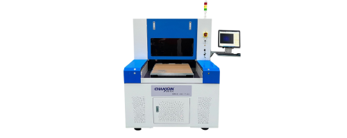
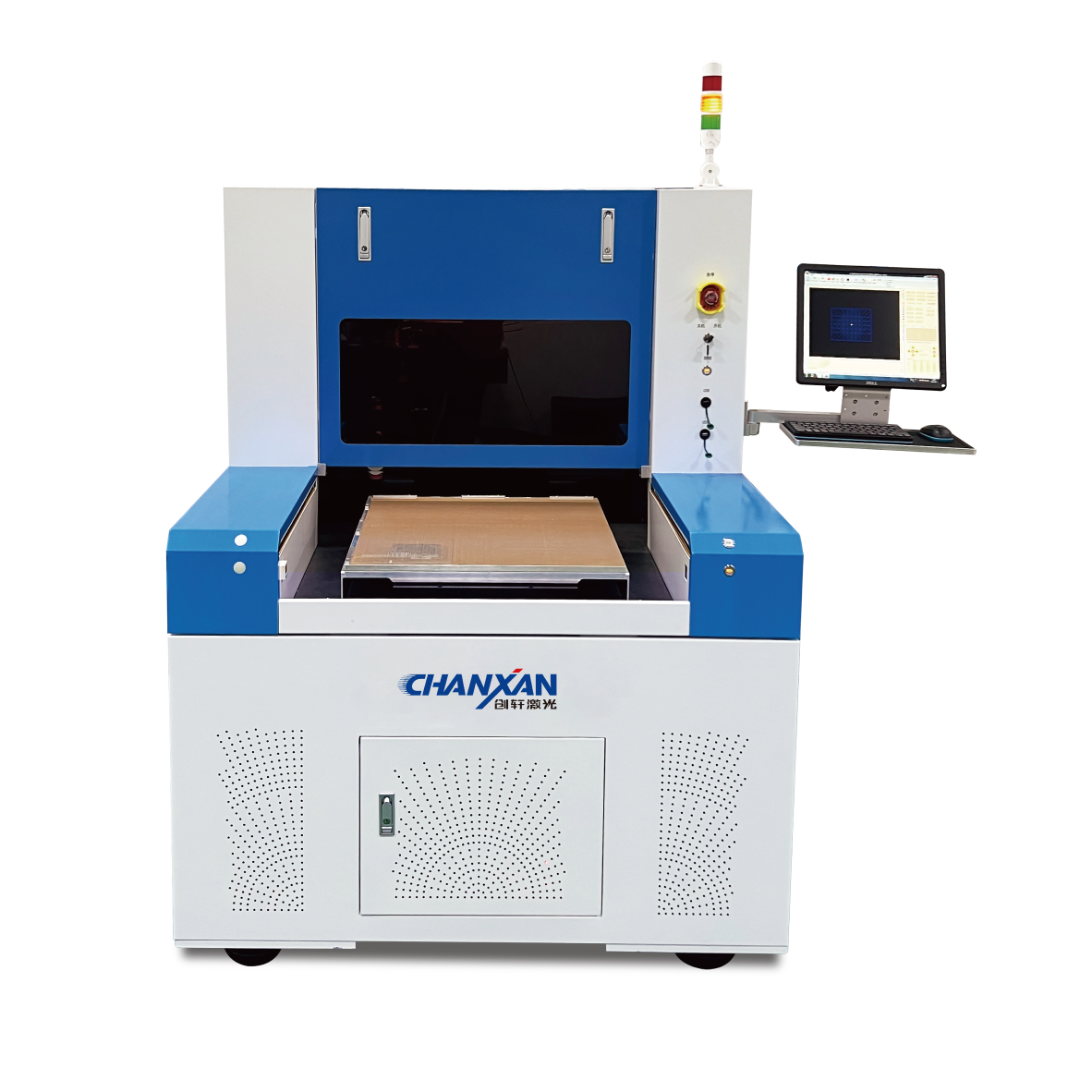
Chanxan offers a production‑ready solution specifically engineered for this demanding application: Chanxan Picosecond Laser System (355 nm/1064nm) is purpose‑built for high‑aspect‑ratio TGV drilling. Its ultra‑short pulse duration (<10 ps) delivers cold ablation with zero micro‑cracks and minimal sidewall roughness – meeting the stringent requirements for subsequent metallisation.
With Chanxan's ultrafast laser systems, manufacturers can transition from process development to high‑volume production with confidence – achieving the via quality, consistency, and throughput demanded by the rapidly growing glass interposer market.